|
|
Quick Sections vs. Intersections An overview of the section and intersection viewing options |
Viewing Block Models as Intersections and 'Quick Sections'
A model is a small-scale representation of a real situation. Models are usually designed and made to be manipulated or processed in such a way as to enhance the understanding of the modeled situation.
Block models represent three-dimensional shapes, volumes, tonnages and grades of solids such as ore zones, waste zones and other volumes of geological or mineralogical interest. Block models consist of blocks, which are cubes or cuboids, stacked together to fill the defined volume as closely as the block sizing criteria will allow.

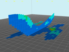
Example of a3Dwindow 'Intersection'
A wealth of options are on offer when it comes to formatting the display of geological block model data. The 3D window provides its own set of unique visualization options. Two such options are the ability to view a block model as a quick section or an intersection.
-
For general information about block models in 3D , click here.
-
For more information on the Quick Section display type, click here.
-
For more information on the Intersection display type, click here.
Block Model Quick Section Displays

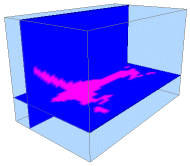
Example of a multiple 3D window 'Quick Sections'
TheQuick Sectiondisplay option found in theBlock Model Propertiesdialog is an excellent method for analyzing the contents of a block model. It is also extremely useful when analysis seismic data as, once a quick section display type has been selected, you are able to use theQuick Section Controlsdialog to sweep backwards and forwards throughout the model in any of the standard 3-dimensional planes (IJ, JK and IK - planar equivalents of X, Y and Z directions) - this feature is not available for theIntersectiondisplay type described in the following section.
Once theQuick Sectiondisplay type has been selected, no further parameters are necessary - the control over the position of the section is then handled by the context-sensitive Quick Section Controls dialog, which is opened by dismissing any open dialogs, then right-clicking the block model description in theSheetscontrol bar (VRFolder) that has already been set up to be displayed as a quick section, and selecting the Quick Section Controls option.
Using this dialog, you can set the general alignment of the section plane to either an IJ, JK or IK orientation, and use the slider bar to traverse the model contents orthogonally to the selected plane, backwards or forwards. Each 'row' of the loaded model table can be viewed separately, using whichever color legend was defined in the Block Model Properties dialog.
Viewing Multiple Sections Simultaneously
View multiple block model sections simultaneously by loading more than one instance of the same data set, and selecting theQuick Section Controlsoption for each. This allows you to control more than one section of the same block model independently, with each section available for display formatting using different legends, if desired:
Block Model Intersection Displays
One of the distinguishing features between an Intersection and a Quick Section is the former's reliance on a previously defined section being present in memory. Another is that an Intersection will have the capability of displaying sub-cells as well as parent cells (as opposed to Quick Sections, which can only display parent cells). In brief, the Intersection display type results in a more detailed display of model data.
The Intersection display option is used to show the plane created by the intersection of a loaded geological model and the selected section plane (remember that these section planes can be defined both interactively using the Sections folder in the Sheets control bar (for more information on creating sections, see Sections overview) or from loaded section definition files. An interactively defined section will always represent a single section, whereas a loaded section file can contain any number of sections, with each being defined by a separate database table row. This single-multiple distinction is important, as will be explained below.
Once in memory, a loaded block model can be rendered with the Intersection option in the Block Model Properties dialog. Selecting this option enables the Intersection Section drop-down list. All currently available sections will be listed here.
-
For all interactively-defined (single) sections, the name shown in the drop-down list will correspond to the same section name as shown in the Sections folder of the Sheets control bar. Selecting a section (and applying the changes) will then re-render the loaded block model as the intersection between the geological model and that section plane. Changing the definition of a section object in memory (using the Section Properties dialog) will automatically update the view of the block model intersection display that is associated with it - once a section is associated, you only have to change the definition of that section for the display of the model to update automatically.
-
If a section definition file is loaded, this will be shown in the list as the name of the file (without its extension) and a '(table)' suffix to indicate it is a loaded database table as opposed to a single section in memory. When a section definition table is specified as the Intersection Section (and the changes applied), the geological model will be shown as the intersection of the specified block model data with the currently active section definition.
he concept of an active definition is important, as you can swap between sections within the same file using that section object's context menu to access its properties, without having to return to the Block Model Properties dialog - once a file is associated, you only have to change the active section for the display of the model to update automatically.
Note that the Intersection display type does not support the use of the Quick Section Controls dialog, as this particular feature is only valid for traversing block model data using a Quick Section (see previous section for more details).
In summary, viewing a block model as an intersection is achieved using the following general procedure:

-
Ensure a geological model is loaded into memory, and is visible in the 3D window. More...
-
Ensure at least one section is defined, and is shown in the Sheets control bar's Sections folder. If the entry was generated by importing a section definition file, ensure that the required section is active, using the Section Properties dialog associated with the loaded file. Otherwise, ensure the interactively-defined section is correctly positioned, using the same dialog.
-
Right-click the block model object to be displayed as an intersection in the Sheets control bar's Block Models folder, and select the Properties option.
-
In the Block Model Properties dialog, select the Intersection display type.
-
In the activated Intersection Section drop-down list, select either the section definition file or defined section plane to be used to render your block model.
-
Click Apply to update the view of the loaded block model (if it is not in view, you could right-click its entry in the Block Models folder and select the Look At option).
| |
Related Topics |
|
|
Block Models Introduction Block Model Properties Dialog Block Model Quick Section Control Dialog Sheets Control Bar Overview |

